When data leaves your laptop and arrives at a server on the other side of the world, how many things had to go right? A USB device sending a single byte to its own host computer is hard enough — Chapter 6 covered the controllers, the interrupts, the memory map. Now imagine doing the same thing across a continent, between machines that have never met.
What Is a Network?
A network is any collection of two or more devices connected in a way that allows them to exchange data. That definition covers everything from two laptops on the same Wi-Fi access point to the global internet linking billions of machines across every continent.
Networks are typically described by their geographic scope. A LAN (Local Area Network) connects devices within a single building or campus — a home network, an office floor, a university lab. A WAN (Wide Area Network) connects geographically separated LANs — the corporate WAN that links a headquarters to regional offices, or the internet itself, which is the largest WAN ever built. In Chapter 6 you met the NIC — the network interface card that connects a machine to a LAN via PCIe. Everything built on top of that physical connection is what this chapter covers.
Why Layers?
Before we name any specific model, ask the more basic question: why do networks need layers at all? Why not one big specification that covers everything from the voltage on the wire to the format of an email?
The short version: nobody could build that. The team that designs an Ethernet cable is not the team that writes a web browser, and the team that runs a fiber backbone across the Pacific is yet a third group. Each of them needs to do their job without holding the whole stack in their head. Layering is what makes that possible — each layer handles one problem and hands off cleanly to the layer above or below.
Layers also let pieces change independently. The TCP packet that carries this page works whether the link beneath it is copper Ethernet, fiber, or Wi-Fi — because TCP doesn't know or care what's underneath. Swap the physical medium and the layers above it never notice. That's the payoff of hiding the details: a web developer can write HTTP without knowing how a wire encodes a 1, and a cable manufacturer can ship a new Cat6A spec without changing a single line of HTTP.
The model used in this book has five layers, from the wire up to your browser:
- Physical — bits as signals on a medium (copper, fiber, radio).
- Data Link — frames between directly connected devices, addressed by MAC.
- Network — packets routed across networks, addressed by IP.
- Transport — connections and ports between applications (TCP, UDP).
- Application — the protocols you actually name out loud (HTTP, DNS, SMTP, SSH).
The rest of this chapter walks up that stack, one layer at a time.
Layer 1 — Signals and Physical Media
No magic happens at Layer 1. A bit is a physical phenomenon — a measurable change in the real world that a receiver can distinguish as either 0 or 1. What varies is the medium through which that change travels.
Copper wire (twisted pair) encodes bits as voltage transitions. A high voltage represents a 1; a low voltage represents a 0. Modern Ethernet uses more sophisticated encoding schemes, but the core idea is the same: the transmitter switches voltage levels at a precise rate, and the receiver samples the wire to reconstruct the bit stream. Gigabit Ethernet does this one billion times per second.
Fiber optic cable encodes bits as light pulses. A pulse of light (photon present) is a 1; no pulse is a 0. Because photons travel at the speed of light through glass and are immune to electromagnetic interference, fiber can carry signals over much longer distances and at far higher data rates than copper. Single-mode fiber used in long-haul networks can span hundreds of kilometers without a repeater.
Wireless (RF) encodes bits by modulating a radio frequency carrier wave. The transmitter varies the carrier's amplitude, frequency, or phase to represent 0s and 1s — a technique called modulation. The receiver measures those variations and reconstructs the original bit stream. Wi-Fi, cellular, and Bluetooth all use this principle; they differ in which frequencies they use, how densely they pack data into the carrier, and how they share the spectrum among multiple users.
Cable Types
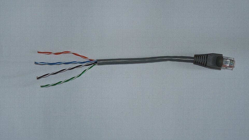
Twisted pair is the most common wired Ethernet medium. Each cable contains four pairs of copper wires twisted around each other — the twisting is not decorative. Electromagnetic interference induces equal but opposite noise voltages in both wires of a pair; because the receiver measures only the difference between the two wires (differential signaling), the noise cancels out. Category ratings (Cat5e, Cat6, Cat6A) describe the cable's specifications and the maximum data rate they support at a given distance. All terminate in RJ-45 connectors.
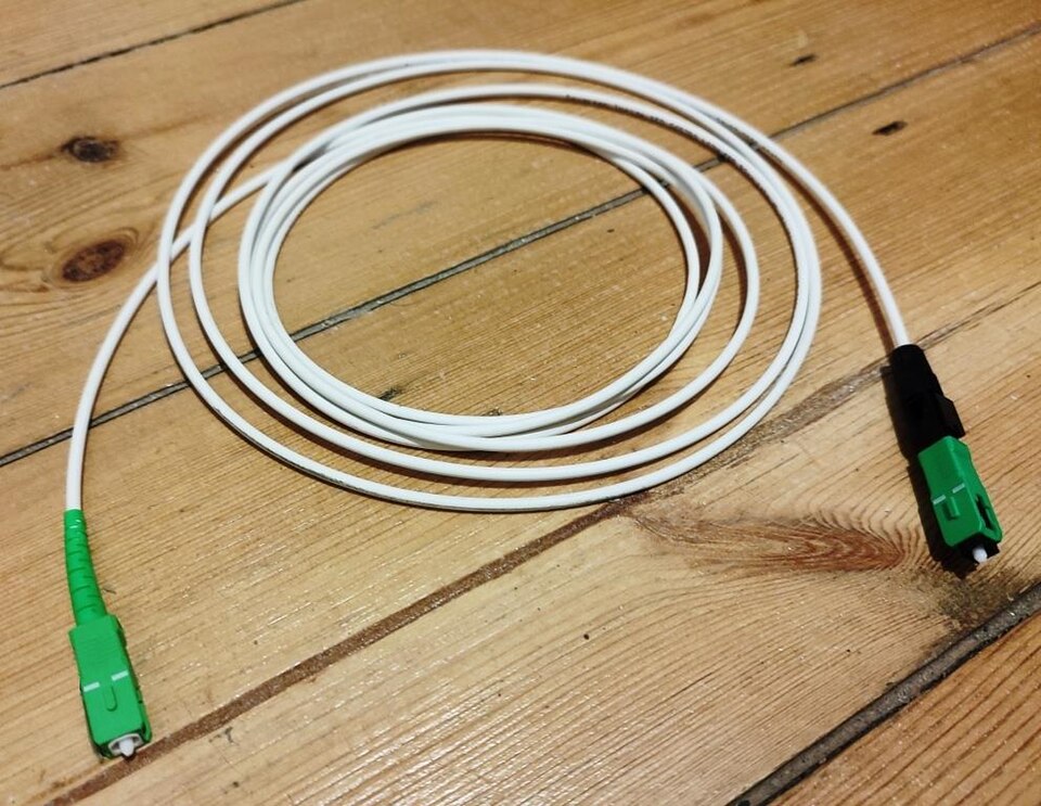
Fiber optic cable carries light pulses through a glass or plastic core. Multimode fiber (thicker core, ~50–62.5 µm) is used within buildings and data centers — shorter distances up to ~550 m at 10 Gbps. Single-mode fiber (narrow core, ~9 µm, one path for light) eliminates signal dispersion and is used for long distances — campus backbones, metropolitan rings, and transoceanic cables. Fiber connectors are LC (small form-factor, common in data centers) or SC (slightly larger, common in telco infrastructure).
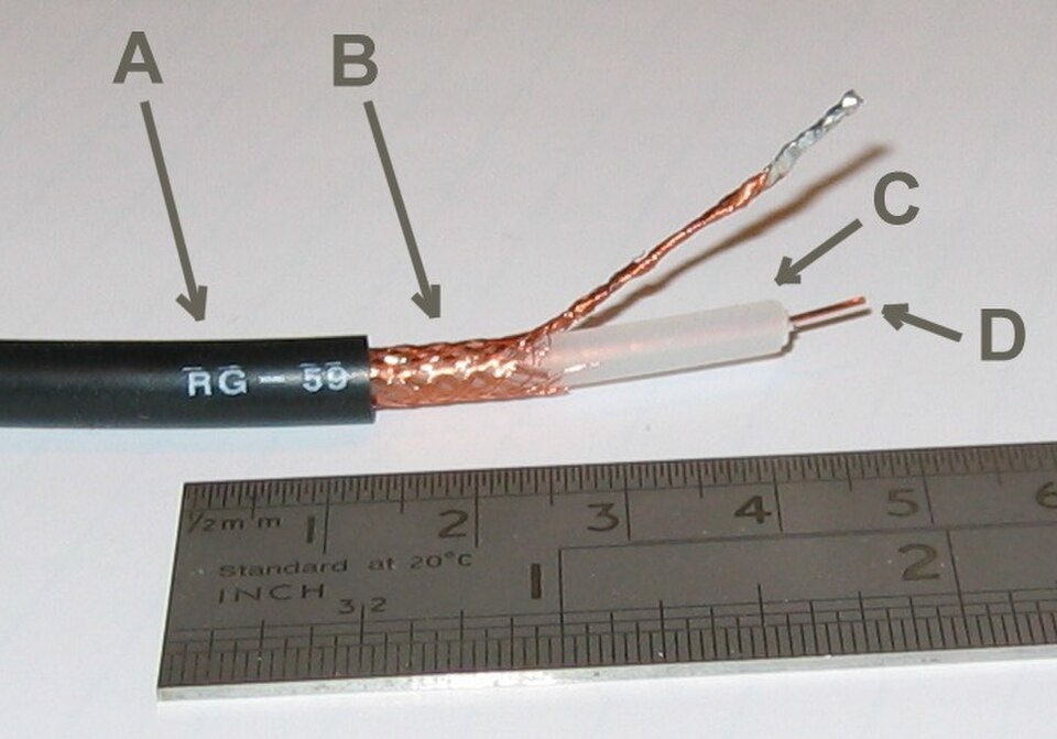
Coaxial cable has a central copper conductor surrounded by insulation, a braided metal shield, and an outer jacket. Coax was the original Ethernet medium and is still widely used for cable television and broadband internet delivery from the ISP to the home (cable modem). In enterprise networking it has largely been replaced by twisted pair and fiber.
With the physical layer in mind, we can now ask how the software layers above it move data from one machine to a specific other machine — and that starts with addresses.
IP Addressing
An IP address is a logical address assigned to a network interface — logical because it is assigned by software and can change, unlike a MAC address which is burned into hardware. Every device that communicates on the internet needs at least one IP address.
IPv4 addresses are 32 bits long, written as four decimal numbers (octets) separated by dots: 192.168.1.100. Each octet represents 8 bits and ranges from 0–255. The 32-bit space allows for approximately 4.3 billion unique addresses — a number that seemed vast in the 1970s but proved inadequate as the internet grew.
IPv4 reserves three ranges of addresses for private use (RFC 1918) — these addresses can be used freely inside any organization's network but are not routed on the public internet. The largest range, 10.0.0.0/8, is typically used by large organizations; 172.16.0.0/12 covers 172.16.0.0 through 172.31.255.255 and shows up in medium-sized networks; 192.168.0.0/16 is the range you'll recognize from every home and small-office router you've ever logged into.
IPv6 addresses are 128 bits, written as eight groups of four hexadecimal digits: 2001:0db8:85a3:0000:0000:8a2e:0370:7334. The 128-bit space provides approximately 340 undecillion addresses — effectively unlimited. IPv6 deployment has grown steadily as IPv4 addresses have been exhausted; most modern operating systems, devices, and ISPs support both protocols simultaneously (a configuration called dual-stack).
Subnets and CIDR
A subnet is a logical subdivision of a network. Subnetting divides a large address block into smaller segments, each with its own defined range of addresses. Routers forward traffic between subnets; devices on the same subnet communicate directly at Layer 2 without involving a router.
Subnet boundaries are expressed using CIDR notation (Classless Inter-Domain Routing) — a slash followed by the number of bits in the network portion: 192.168.1.0/24 means the first 24 bits identify the network (leaving 8 bits for host addresses, so 256 addresses with 254 usable). /16 leaves 16 bits for hosts (65,536 addresses). /30 leaves 2 bits for hosts — exactly four addresses, two usable, common for point-to-point router links.
Why subnet? Three reasons matter in practice: broadcast control (Layer 2 broadcasts are contained within a subnet), security (routers can apply access control lists between subnets), and organization (subnets can map to physical floors, departments, or functions, making the network easier to manage and troubleshoot).
DNS
IP addresses say where data is going; DNS is what translates the name you type into one of those addresses. Computers route traffic using IP addresses. Humans use names. The Domain Name System is the internet's distributed phone book — it translates human-readable names like www.example.com into IP addresses like 93.184.216.34. As promised in Chapter 9: this is how it works.
DNS is a hierarchy. At the top are the root name servers (13 root server clusters worldwide), which know nothing about individual domain names but know where to find the Top-Level Domain (TLD) servers responsible for .com, .org, .edu, and country codes. TLD servers know which authoritative name servers are responsible for each registered domain. The authoritative server for example.com holds the actual records that map names to IPs.
When your device needs to resolve a name, it sends a query to a recursive resolver — typically provided by your ISP or a public service like Google's 8.8.8.8 or Cloudflare's 1.1.1.1. The resolver does the heavy lifting: it walks down the hierarchy on your behalf, caches the results, and returns the answer.
DNS records come in several types. The ones you will encounter most often:
| Record Type | Purpose | Example |
|---|---|---|
| A | Maps a hostname to an IPv4 address | www.example.com → 93.184.216.34 |
| AAAA | Maps a hostname to an IPv6 address | www.example.com → 2606:2800:… |
| CNAME | Alias — points one name to another name | blog.example.com → www.example.com |
| MX | Mail server for a domain | example.com → mail.example.com (priority 10) |
| SRV | Service location (used by AD, SIP, etc.) | _ldap._tcp.company.com → dc1.company.com:389 |
| PTR | Reverse DNS — IP address to hostname. Mail servers check PTR records to confirm that a sending IP matches the domain it claims; a missing or mismatched PTR is a red flag for spam filters. | 34.216.184.93.in-addr.arpa → www.example.com |
| TXT | Arbitrary text; used for SPF, DKIM, domain verification | "v=spf1 include:…" |
Names resolve to addresses; addresses get packets to the right machine. The remaining question is which application on that machine should receive them — and that's what the transport layer answers.
TCP and UDP
IP gets packets to the right machine. Port numbers — 16-bit integers from 0–65535 — get them to the right application on that machine. When your browser connects to a web server, the server listens on port 443 (HTTPS); your browser is assigned a random high port (e.g., 54231) for the reply. The four-tuple (source IP, source port, destination IP, destination port) uniquely identifies every active connection on the network.
TCP (Transmission Control Protocol) is connection-oriented. Before any data flows, the two sides perform a three-way handshake to establish a connection and agree on initial sequence numbers. TCP then numbers every byte of data, requires acknowledgments, detects lost segments and retransmits them, and reorders out-of-sequence delivery at the receiver. The price of all this reliability is overhead — three round trips to establish, additional round trips to close, retransmission delays when packets are lost. Use TCP when data must arrive complete and in order: web pages, file transfers, email, database queries, SSH sessions.
UDP (User Datagram Protocol) is connectionless. Each datagram is fired at the destination with no handshake and no acknowledgment. If a datagram is lost, UDP does not notice and does not retransmit. Use UDP when you need low latency or real-time delivery more than you need completeness: video streaming, voice calls, online gaming, DNS queries (a single small request/reply — retrying is faster than establishing TCP).
We've assumed all along that a device has an IP address, a gateway, and a DNS server. Where do those settings come from? On most networks, they're handed out automatically the moment a device plugs in.
DHCP
For a device to communicate on a network it needs four pieces of configuration: an IP address, a subnet mask, a default gateway (the router's IP), and a DNS server address. A network administrator could configure these manually on every device — but DHCP (Dynamic Host Configuration Protocol) automates the process.
When a device joins a network it broadcasts a discovery message. A DHCP server responds with an offer. The device requests the offered configuration, and the server confirms the lease. This four-step exchange — Discover → Offer → Request → Acknowledge (DORA) — completes in milliseconds. The server grants a lease for a defined period (often 24 hours for wired clients, shorter for wireless); if the device is still on the network when the lease expires, it renews automatically.
In enterprise environments, the DHCP server is typically a Windows Server or Linux machine (often the same server running DNS), not the router. The router is configured as a DHCP relay agent, forwarding DORA messages between the client and the server. This allows one central DHCP server to service multiple subnets.
Common Ports and Protocols
Memorizing the common port numbers is the kind of thing that takes ten minutes and marks you as someone who knows what they're talking about for the rest of your career. Port numbers below 1024 are called well-known ports and are reserved for standard services. You'll see them in firewall rules, network captures, log files, and server configurations daily.
| Port | Protocol | Transport | Purpose |
|---|---|---|---|
| 20 / 21 | FTP | TCP | File Transfer Protocol (data / control) |
| 22 | SSH | TCP | Secure Shell — encrypted remote terminal and file transfer (SCP/SFTP) |
| 25 | SMTP | TCP | Email delivery between mail servers |
| 53 | DNS | UDP (and TCP for large responses) | Domain Name System queries |
| 67 / 68 | DHCP | UDP | Dynamic Host Configuration (server / client) |
| 80 | HTTP | TCP | Web — unencrypted |
| 110 | POP3 | TCP | Email retrieval (older; downloads and deletes from server) |
| 143 | IMAP | TCP | Email retrieval (modern; keeps mail on server) |
| 389 | LDAP | TCP | Directory service queries (Active Directory) |
| 443 | HTTPS | TCP | Web — encrypted with TLS |
| 445 | SMB | TCP | Windows file and printer sharing |
| 587 | SMTP (submission) | TCP | Email submission from client to outgoing mail server |
| 636 | LDAPS | TCP | LDAP over TLS |
| 3389 | RDP | TCP | Remote Desktop Protocol — graphical Windows remote access |
Chapter 11 takes the protocols you just learned and puts them inside actual buildings — the switches in your wiring closet, the firewall at the network edge, the access point above your desk.